Preface
Following post is adapted from my graduation thesis in SAE Audio Engineering programme.
I continually see questions and confusion regarding gain staging, and this document is still relevant even though I wrote it in 2012. While some parts of it regarding analog setups may not have the same level of appeal anymore, it’s still important to know where we are coming from even working fully inside the box.
Enjoy!
Introduction
Digital Summing, High Dynamic Range, In-the-Box Mixing, HD Audio, 128x Oversampling, 64 bit Internal Processing…
We hear all these words nowadays, and we usually take them for granted, as these concepts refer to things that are happening in the background while we’re recording or mixing our audio materials. We seem to be free from the meticulous fiddling, calibration and gain structuring of analog equipment, as our dynamic ranges gets higher and noise floors gets lower.
However, even the most “digital” equipment have an optimum working range and in order to fully utilize the wide dynamic range that modern equipments provide us, proper gain structuring remains a vital part of our workflow. This is also important as 99% of all music album sales are CDs or Digital Formats1 which requires reducing the dynamic range, while still maintaining an acceptable level of noise floor.
In the light of these information, this research paper aims to determine the best possible practices regarding gain structure in various systems, by referring to fundamental concepts that affect gain structure and our perception of gain such as bit depth, dynamic range, headroom, metering, decibels, and calibration.
Fundamental Concepts
In order to understand gain structuring in all its depth, one should have the necessary knowledge of the elements that deals with gain, audio levels, and differences and similarities between digital & analog audio.
Also, benefits of attaining a proper gain structure or problems that can arise with improper level adjustments must be fully comprehended so that the important question of “why?” can be answered easily.
Components of Signal Flow
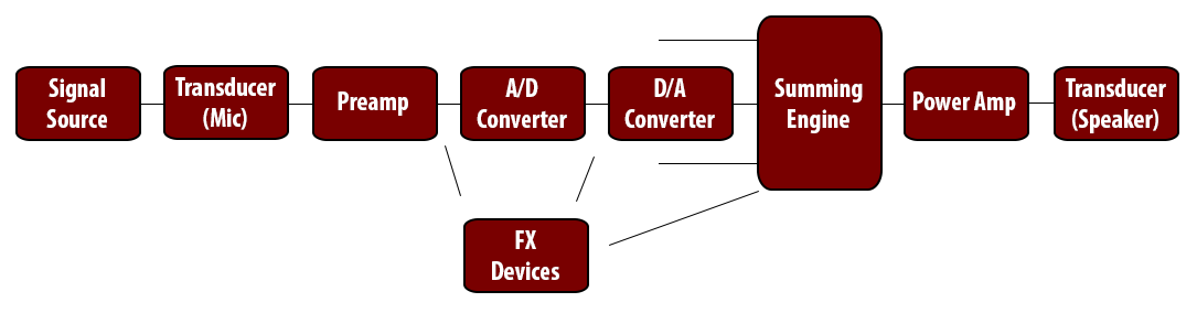
A typical Audio Signal Flow regarding gain structure consists of the following components:
-
Signal Source: This is the original sound we want to process. This may be a guitar, a human voice, a digital signal generator; basically anything that produces a sound can be our signal source. In terms of gain structuring, our ability to modify the amplitude of a signal source is limited (unless the source is purely digital), as this also often changes the natural timbre and tone of the signal. Think of a vocalist keeping his/her volume down to control gain, it’s not natural.
-
Transducer: This is the device that converts the sound pressure waves (acoustical energy) of acoustical signal sources into electrical signals (or vice versa). Microphones, pick-ups, speakers and headphones are primary examples for this. Gain control in transducers are also limited as microphones or other transducers offer very few controls regarding gain structure.
-
Preamp: Preamps are devices that take low-level signals from transducers and converts them to line-level signals so the succeeding equipment can process the signal. Preamps are the primary and most important components in achieving proper gain structure. If the level of a signal coming from a transducer is not adjusted properly at the gain stage of the preamp, it may be too low or too high at its output, which affects the operation of all the succeeding components. The popular saying “Garbage in, garbage out” fits especially well here.
-
A/D & D/A Converters: Now, if at some point, the signal is wanted to be processed in the digital domain, we must talk about Analog-to-Digital conversion. To do this, the continuous analog signal must be sampled and approximated by frequency and amplitude, and converted to numbers that represent them. From gain structure perspective, the most important aspect of the converter is its usable dynamic range, or its SNR (Signal-to-Noise Ratio). To utilize the full dynamic range and lower the noise floor the converter has to offer, the level of the signal going into the converter, as well as coming out of the preceding equipment must be adjusted properly, and must stay in the converter’s optimum working range, and proper headroom should be left in order to be prepared for any clips resulting from quantization errors2. When we want to represent our signal in the analog domain (i.e. speakers) again, that is called Digital-to-Analog conversion.
-
FX (Effect) Devices: These include -but not limited to- dynamic processors, equalizers and time-based effects such as reverb, delay, chorus, etc. These processors may be used anywhere in the signal chain between the preamp and the power amp, in the form of an analog equipment, a digital signal processor (DSP) or a computer software (DAW plug-in). Each FX device may have its own input gain, output level, or in the case of digital processors, its own A/D & D/A conversion. Each device also has its own challenges regarding proper gain adjustments, for example tube devices may require high enough input to saturate the tubes, or digital processors with mediocre converters need an input high enough that the noise floor doesn’t become an issue.
-
Summing: Whenever we want more than one signal to be combined into a single audio signal, we are talking about summing. Summing can be in the analog domain in an analog mixing console, where it’s called Analog Summing; or it can be digital and take place inside the computer software or a digital mixer, where it’s called Digital Summing. Both approaches has its strengths and weaknesses, and these will be discussed in a forthcoming chapter thoroughly.
-
Power Amp: When we want our line-level signals to be heard from an output transducer (speaker, headphone), we use a power amplifier to amplify this signal so that it’s able to drive a speaker or a headphone.
Gain Structure Elements
This section will cover the detailed explanations of elements that are closely related to proper gain staging. Understanding of these concepts is critical in order to explain what proper gain staging is.
Bit Depth
The bit depth refers to the theoretical dynamic range or resolution of digital audio as it’s quantized to the specified number of bits during the sampling process.
Bit depth directly affects a system’s signal-to-noise ratio, and it’s usable dynamic range. Higher bit rates provide more resolution (wider dynamic range) and lower noise floors. It’s generally accepted that “for each 1-bit increase in bit depth, the SNR will increase by 6 dB”3. This gives us a theoretical dynamic range of 96 dB for 16 bit systems and 144 dB for 24 bit systems.
Dynamic Range
Dynamic range is the difference between the largest and smallest signal a system can record or reproduce; where the lower end is often called the “noise floor”, and the higher end “peak level”.
In analog systems, as dynamic range is rather limited (i.e. tape recorders peaking at 90 dB and radio broadcasts around 50 dB), gain staging plays a crucial role in keeping the noise floor down.
Generally speaking, the higher the dynamic range (thus lower the noise floor), the less susceptible the system is to inadequate signal levels and improper gain staging, as any apparent dynamic range and noise floor beyond 120 db is outside the hearing range of the average human ear4.
Another application that can increase the perceived dynamic range is dithering. Renowned engineer Bob Katz described dithering as:
“In an analog system, the signal is continuous, but in a PCM digital system, the amplitude of the signal out of the digital system is limited to one of a set of fixed values or numbers. This process is called quantization. Each coded value is a discrete step… if a signal is quantized without using dither, there will be quantization distortion related to the original input signal… In order to prevent this, the signal is “dithered”, a process that mathematically removes the harmonics or other highly undesirable distortions entirely, and that replaces it with a constant, fixed noise level.”5
Headroom
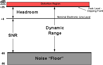
Referring to the figure above, we can define headroom as the safety zone between a given signal and the peak level of a given system be it analog or digital (See Figure 2)6.
Leaving enough headroom during any stage of gain structuring is important, as it allows us to deal with sudden increases in the audio signal effectively, and avoid digital clipping in the converters due to quantization errors.
Benefits of Proper Gain Structure
Proper gain structuring in any stage of the signal chain has the following apparent benefits:
- Increase in perceived dynamic range,
- Decrease in perceived noise floor.,
- Better quality A/D & D/A conversion by avoiding digital clipping and utilizing the full dynamic range,
- Overall Increase in signal quality as the signal stays in the optimum working range of equipments,
- Better dealing with analog distortion and digital clipping.
Problems of an Improper Gain Structure
Failure to achieve proper gain structure causes many problems in all stages off the signal chain. These include:
- Decrease in perceived dynamic range,
- Elevated and problematic noise issues,
- Digital clipping due to quantization errors on the higher end of the dynamic range,
- Overloaded or underutilized equipment,
- Signal more prone to digital clipping or analog distortion.
Metering & Calibration
Knowing how to read signal meters is essential in order to judge the gain adjustments correctly. There are different types of meters and measurements which shows different aspects of a given signal. Understanding these differences allows us to base our gain staging on accurate terms.
Definition of Concepts
Signal Measurements
We measure a given signal’s loudness using Sound Pressure Level (SPL), in decibels, which “is a logarithmic measure of the effective sound pressure of a sound relative to a reference value.”7. The common reference level is 20 µPa RMS, which is considered as the threshold of human hearing8.
We often use two different decibel scales, dBu (Decibels Unloaded) and dBFS (Decibels Full Scale):
“The dBu scale measures the analog voltage level in our equipment and cabling, with 0 dBu calibrated to about 0.775 volts.
dBFS indicate signal levels as defined by the values of the digital samples of an analog signal that as been converted to digital data. The top of the scale (0 dBFS) indicates a digital value where all the bits of a digital sample have a value of 1.”9
Types of Metering
-
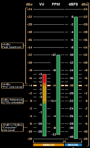
VU (Volume Unit) Meters: These are traditional meters with a slow response (~300 ms), which shows the average loudness of the given signal instead of its sudden peaks and dips. These are calibrated from -20 to +3 dB, where 0 dB VU = Line Level (usually +4 dBu).
-
PPM (Peak Program Metering) Meters: This type of meters have a faster response time (~10 ms) to show the transient peaks of an incoming signals. These are typically calibrated from -12 to +12 (+14,+18) dB, where 0 dB PPM = 0 dBu (However this 0 dB PPM may be calibrated to any desired dBu value).
-
dBFS Meters: These meters are digital meters either hardware or software, which represent binary values of a converted signal, and can either show peaks or average signal levels. These do not represent analog voltages or signal levels, thus are not calibrated according to these. The actual calibration occurs inside the ADC circuit, where -18 dBFS often equals +4 dBu.
Reading & Calibrating Meters
Each of the aforementioned meters represent audio signal level differently, and each needs a different approach when deciding where in the meter scale our signal should reside (See Figure 3)9.
As mentioned before most professional audio equipment have an optimum working range regarding signal level, and this is called the “Line Level”. It’s safe to assume that in order to achieve the benefits of proper gain staging, we should aim for our signal to be at around this line level, and make our gain adjustments and meter readings accordingly.
Nominal Line level is accepted as +4 dBu in most professional audio equipment10. Assuming the meters are calibrated as mentioned (standard accepted calibration), the optimum level for any given signal can be summarized as:
-
VU (0 VU = +4 dBu): As VU meters show the average level, the signal should be around the 0 VU mark most of the time.
-
PPM (0 PPM = 0 dBu): PPM meters are more responsive to transient peaks, so we should observe peak values closely, leave enough headroom so that the signal stays away from the distortion zone at all times, and aim for around 0 to +4 dB PPM for most of the signal, with occasional peaks allowed for up to +8 or +12 dB PPM. Any higher level may be risky, prone to distortion and doesn’t leave enough headroom.
-
dBFS (-18 dBFS = +4 dBu at ADC): At the converter stage, any signal going over 0 dBFS will be digitally impossible to represent and will be clipped. Therefore we should allow enough headroom so any occasional peak can be dealt with by the ADC without going over 0 dBFS. Assuming the digital meter is in peak mode; for a 24 bit converter, average signal level around -18 dBFS with transient peaks up to -12 dBFS can be a good compromise between optimal signal level and noise floor. Once the signal is in the digital domain, things start to change. For example, 32 bit or 64 bit floating point internal mixing or processing engines of DAWs or plug-ins allow the digital signals go over 0 dBFS without clipping. This will be described in the next chapter.
Mixing and Summing Environments
After familiarizing with the important concepts, it’s time to look at gain structuring in real world usage, on specific equipments. As analog and digital systems show differences and similarities on all stages of gain structuring, these systems will be investigated separately, with a detailed comparison summarizing these differences and similarities will be given in a following section.
Gain Staging in an Analog Setup
Analog systems are inherently more susceptible to improper gain staging, due to the lower dynamic range they offer, proneness to noise and generation loss (signals being carried between equipments in the analog domain [cables, tape systems etc.] lose their quality in every step).
That being said, analog systems are generally more forgiving when it comes to signal overload, as the headroom above the nominal line level is tend to be left higher (though noise level is higher, too) and analog distortion is less irritating or even desirable in some cases (tape compression, tube saturation, etc.)
Next few sections will investigate some of the major components in an analog setup in detail, regarding gain structuring, and provide ways to achieve optimum levels and highest signal quality.
Preamps
Whether built into a recording console, or just a standalone unit, preamps are the beginning of the gain structure chain where our low voltage signals are converted to nominal line level (+4 dBu) in order to feed the succeeding equipment with proper levels.
Common controls and indicators on preamps include:
-
Gain Controls: These are the controls where we adjust the amplification of our incoming signal. As this gain control determines how much above the noise floor our initial signal will be, how wide our dynamic signal will get, and how much of a headroom will be left, it’s safe to say that this is the single most important control in the whole gain structure chain.
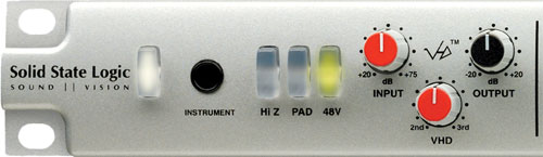
Different manufacturers label the gain control differently (gain, input gain, trim, drive, etc.), or some units have 2-stage gain controls (a coarse gain adjustment, and a fine trimming adjustment). Some tube units have a separate “drive” knob for adjusting the tube saturation in addition to the normal gain control, and some higher end solid-state units have harmonic drive circuits like the SSL’s X-Logic preamp with Variable Harmonic Drive11 (See Figure 4).
Although this “input gain” control approach is sufficient for sculpting the sound with enough amplification, drive and headroom, without an adjustable “output gain” control, we risk of running the output of the preamp too hot for the next equipment in the signal chain. That’s why more sophisticated units have a dedicated output gain control, which allows us to drive the internal preamp circuit as hot as we want (if the sound we’re searching for requires it) and not worry about the fact that output level of the unit may overload the next equipment in the chain. The “output gain” then becomes the most important control as it allows us to keep our signal level as close to nominal line level as possible.
-
Pad: Some signal sources may be too hot for a preamp to handle, even with the lowest gain settings. That’s why most preamps offer a pad switch to attenuate the incoming signal (-5, -10, -20, or adjustable dBs depending on the unit) so that we can keep the preamp from distorting and utilize the gain control for sculpting the sound.
-
Meters & Indicators: Most preamps offer some kind of indicator to judge the incoming signal level correctly. These may be in the form of a simple no-frills “clip” light (for indicating that the signal is too hot and may be distorted), or more sophisticated VU and PPM metering for both input and output levels.
These allow us to visually observe the signal level for transients or overloads, and make our gain adjustments more precise. By using the general metering guidelines discussed in the 3rd chapter (keeping the output signal level around the nominal line level), we can visually ensure that our signal stays in the optimum working range.
Some preamps offer no indication of signal level (such as the aforementioned SSL XLogic VHD Pre), and depend on the input level metering of the next equipment in the signal chain (meter-bridge on a mixing console, or level meters of an A/D converter) for visual indication.
Analog Mixing Consoles
Mixers are devices that “mix” two or more sources and sum their outputs into a master bus in a specified number of channels (Usually 2-channels [stereo] in music production).
As most professional audio equipments, mixers operate at line level, thus proper gain staging is essential in order to stay in the mixer’s optimum working range.
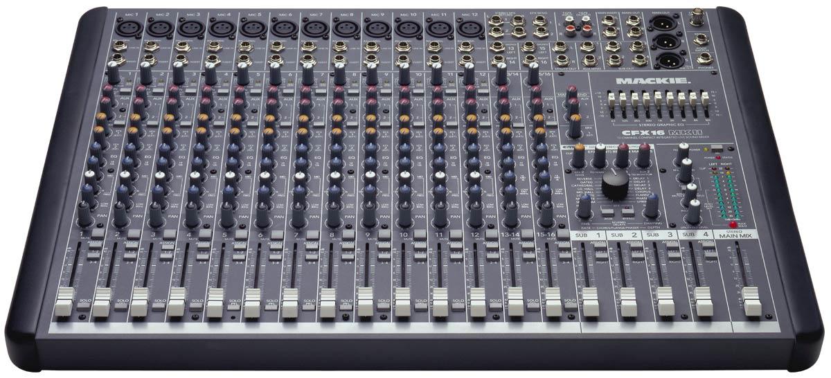
Mixers consists of several gain stages and in order to keep our signal level at the highest quality possible, we should ensure that they are properly adjusted. Looking at these stages one-by-one:
-
The Channel Strip: This is where our signal enters the mixer, adjusted and routed to a bus and/or sent to an auxiliary send. The input of a channel strip may include a microphone preamp, or it may accept line level sources only. Regardless of the input source, proper gain structuring procedure in the channel input stays the same:
- Set the input correctly, turn gain control to zero,
- Keep all channel strip processes bypassed or flat (EQ, Dynamics, Inserts, etc.),
- Keep channel fader at unity (0 mark),
- Ensure that we’re metering the correct channel (solo the channel if the mixer don’t have separate channel meters.),
- While signal is present, adjust the gain control so that the meter stays around 0 VU, or +4 PPM (nominal line level)
-
Channel Insert: While there’s often no gain control for external inserts on a mixing console, it’s advised that general proper gain staging principles discussed before are followed on the external processors in the insert path, so that the signal quality is not compromised.
-
Auxiliary (Aux) Sends: Aux sends allow us to split the signal at the channel strip and send them to a separate auxiliary bus. These auxiliary buses can be feeding headphone amps, or external effect units. While the aux master level controls the output level going into these external devices, we should still make sure the signal level is adequate in the relevant aux send, considering multiple signals from different channels may be feeding the same aux, thus effectively making the channel “aux send” an “input gain” control for that auxiliary bus.
-
Auxiliary (Aux) Returns: Aux Returns are basically channel strips, often with limited functionality, that are reserved for returns from external outboard equipment, which are fed from aux sends. Thus, general principles discussed in the channel strip section also apply here.
-
Mix Buses (Main / Sub): This is where the signals from different channel strips are summed and mixed, as groups or as main mix. This is the output of the summing engine. As we start to mix more than one signal, the cumulative level of summed signals will start increase. It’s good practice to keep the main mix also around nominal line level, or 0 VU; in order to do that, we use the channel faders to alter individual signal levels (think channel faders as input gain controls for the summing engine), and we use the master fader as the mixer’s output level control. Although 0 VU is an acceptable level to aim for the main mix (also for most of the signal chain), as mixing console circuits and summing engines differ substantially, driving the summing engine hotter or cooler than 0 VU may have more desirable effects because of the analog circuit characteristics. Higher-end consoles from Neve, SSL or Harrison for example deal with hot signals superbly, and their desirable drive characteristics made a lot of engineers mix hotter than the recommended 0 VU12.
Tape Recorders
Analog tape recorders are 2-track or multitrack recording devices that record incoming signals into a magnetic medium (tape). Although their usage is substantially diminished in the modern music production world, their unique compression and sound coloring characteristics still enable them to find a place on many engineers’ studios (See Figure 6)13. Even software emulations of classic tape recorders are among the most selling plug-ins for various computer systems14.
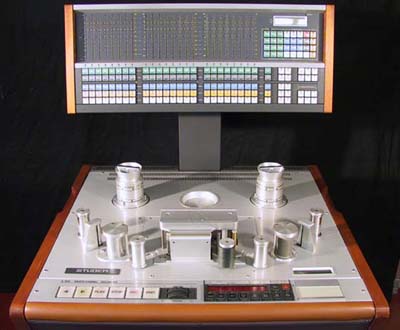
In gain structuring point of view, at the input stage, tape recorders behave like most professional audio equipment and expect, and optimally work with signals at line level (+4 dBu). Channel input meters are visual indicators of the incoming signal level.
However most tape recorders also include a recording level, and this level needs to be calibrated by a professional according to the tape formulation used and level of tape saturation desired. Once calibrated, any source signal, with tape’s input gain set properly, will have the desired amount of tape saturation and good dynamic range with sufficient headroom and minimal noise.
Effect (FX) Units
As mentioned earlier, FX units may be used anywhere in the signal chain between the preamp and the power amp stages, and here too, gain structuring principles are to be followed in order to keep the signal quality as high as possible.
The rule of thumb here is to keep the signal chain as short as possible, to avoid generation loss and signal degradation between different equipment. Keeping the signal at line level going from one device to another ensures that we are keeping the noise level at minimum, while still achieving sufficient headroom.
Most outboard equipment will have input and output level controls, and this helps a great deal while adjusting the signal level to stay around line level. For units without an input gain control, ensuring that the preceding unit’s output level is at line level; and conversely for units without an output level control, ensuring that the succeeding equipment’s input gain is set at line level avoids signal degradation.
Equalizers often change the overall loudness of the incoming signal, thus it’s advised that their output level is set so that the signal stays at nominal level.
Compressors and other dynamic processors change the level of the incoming signal drastically as such the output level or “make-up gain” control should be set that the output signal level stays close to the input signal.
Some tube units or units with internal drive circuits nearly always have output level controls. So we can still overdrive internal circuit to get the desired effect we want, while making sure that our signal stays at line level at the output.
Gain Staging in a Digital Setup
First there was the PCM coding, then the digital tape recorders. Then came computers, hard disk recorders, digital audio workstations, plugins, digital mixers. Today, we live in a world where no music production is completed without entering the digital domain in one way or another.
In a gain staging perspective, digital systems differ significantly from analog systems. First and foremost, there is no generation loss in digital audio, as all that is carried between equipment is mathematical representations of the actual analog signal. Also digital systems offer superior dynamic range in the conversion stage (usually 24 bits - 144 dB theoretical) and practically infinite dynamic range in the processing and summing stages (32+ bits floating point, over 1,500 dB).
Next few sections will investigate some of the major components in a digital setup in detail, regarding gain structuring, and provide ways to achieve optimum levels and highest signal quality.
Analog to Digital Converters
Analog to digital converters (ADC) are the entry point of our signal into the digital domain. As digital conversion is still a tedious process often requires dealing with errors, levels etc., quality converter design is fundamental in keeping the signal quality as high as possible in the digital world.
As digital metering (dBFS) is just a representation of signals in mathematical values, there is no actual calibration against a voltage or dBu level in the digital domain. Instead the actual calibration is made at the input stage of the conversion. While there’s no accepted standard in calibrating the signal level at the converter input into a value in the dB Full Scale, we will assume the most used calibration level of +4 dBu = -18 dBFS throughout this chapter. This level is used in some higher-quality converters, and is one of the user selectable values in others (See Figure 3).
So, line level signals at +4 dBu coming into the input of the converter, will translate to -18 dBFS at its output, which gives us not just a sufficiently high level above the noise floor, but also enough headroom to deal with any peaks or sudden transients in the signal.
The trick here is to get acquainted with the specifications of the converter thoroughly, as there’s no accepted standard among manufacturers regarding voltage levels and input calibration.
Digital Audio Workstations (DAW) and Digital Mixers
This is where things get interesting. Once our signal is in the digital domain, we are usually doing our processing, mixing and summing inside a computer software, or inside a digital mixer (as basic operating principles for both are essentially the same).
While still most DAW manufacturers tell us to keep our recorded signals as close to 0 dBFS as possible without clipping, this has no practical benefits in today’s 24 bit converters with exceptionally low noise levels. On the contrary, it’s quite inadvisable since it leaves us little or no headroom.
That being said, most modern DAWs and digital mixers (and even plug-ins) have 32 or 64 bit floating point internal processing and summing engines which make proper gain staging practices seem quite irrelevant, as signals are allowed to go much higher than 0 dBFS without clipping or overloading. Overloading all of your DAW channels while keeping your master fader down so that the output does not clip (and your DAC is not overloaded), will have no effect on the quality of your signals15. Because the internal summing engine of the DAW is dealing with the overloaded signals easily as it’s operated in 32 (or 64) bits using floating point math.
So, as long as you don’t overload your digital to analog converter (by keeping your mix level under 0 dBFS), you’re pretty much free regarding your individual channel levels. While theoretically seems tempting, this freedom has some disadvantages in the practical sense, mainly in metering and plug-in effect usage.
Metering in overloaded channels is not visually helpful, as most of the time the DAW meters stays in the very high end of the dBFS scale.
There are also signal quality issues once effect plug-ins come into the picture, which brings us to the next section:
Plug-ins and Effects
Most modern plug-ins, not unlike DAWs, have also 32+ bits internal processing engines, which allow them to deal with internal overloads and signals above 0 dBFS. But still, some plug-ins, especially dynamic effects (compressors, etc.) don’t have an input level control, and behave unexpectedly if inserted into a channel with an overloaded signal, rendering some of its controls unusable and producing unwanted artifacts (See Figure 7)16.
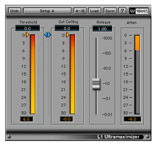
This can be avoided using gain/trim plug-ins before the offending plug-in, or by simply using lower signal levels in the first place. As mentioned before, there’s practically no need to constantly hit 0 dBFS or above in today’s technology.
“Running a Digital mix right to the top of the scale is like running your SSL mix buss where the VU meters are slammed all the way to the right and you are constantly hitting it at +25. No one will get a good sound running the desk like that. You won’t get a good sounding mix in digital either.”17,
Then there is the issue of analog modeling plug-ins. As modeling technology got sophisticated, modeled plug-ins got sonically indistinguishable from their hardware counterparts18. That means those plug-ins behave exactly like the hardware they’re modeled after, which includes gain staging, and an optimum working range at nominal line level. For example, while your DAW can handle 12 dB above the 0 dBFS signals easily, when going into a Waves VEQ4, this level translates as +34 dBu (considering the plugin is calibrated at +4 dBu = -18 dBFS like the hardware unit19) at the plug-in input! For a hardware emulation expecting a line level input, this means overloading the plug-in’s internal circuit and sonically altering the way the plug-in supposed to work. Skip Burrows (2009) from Sunrise Studios summarize this as:
“Plugins use the same reference as real equipment. Never try and drive them to the top of the digital scale. Don’t try and make your mix look like a master. You don’t do that on an analog console, so why do we do it in-the-box?”
One other advantage of practicing good gain staging in a modern DAW environment is that any analog outboard units inserted into the signal flow (as most modern DAWs allow inserting hardware signal processors via an I/O pair of the audio interface used) benefit from the proper levels going out of our converters. This practice ensures that these devices stay in their optimum working range (line level) and our signal quality is not compromised.
Differences & Similarities between Analog & Digital Systems
Up until this point, we looked at the way gain staging works at analog and digital units separately, while drawing attention to any relevant similarities or differences. This section will aggregate and summarize these comparison elements, and enable us to judge any weaknesses or strengths these systems have clearly.
Similarities between the two systems may be summarized as:
- If you rule out the digital conversion process, signal flow stays pretty much the same on both systems
- Maintaining a sufficient headroom is an important part of the gain staging process in both systems, as it allows to maximize the efficiency of the equipment used.
- We still need to deal with noise issues, which may be present in the source signal or caused by any equipment in the signal chain.
- Both systems are prone to signal distortion and overloads should be carefully observed.
While we observe these similarities, there are also some fundamental differences in operation of analog and digital systems. These include:
- In analog systems we deal with electrical currents and voltage levels, whereas digital audio is just a mere numerical representation of these voltages.
- Digital audio does not have generation loss, as signals that are carried are just numbers; but analog audio signals lose some of its quality in every step of the signal chain.
- Digital systems offer theoretically superior dynamic range (144 dB for 24 bits), and excellent noise performance compared to traditional analog systems.
- Digital conversion is still not a perfected process, prone to errors (quantization errors, jitter, etc.) and converter quality still plays a major part in the final sound.
- While analog summing devices are limited with whatever dynamic range the device has to offer, floating point processing allow digital summing to deal with signals in excess of 1,500 dB!
Conclusion
These research shows that, in a pro audio environment, in order to keep our signal quality as high as possible, we should be paying attention to our gain structure in every stage of the signal chain, which in turn can easily be summarized with these two words: “Line Level”.
Nominal Line Level is an industry accepted standard signal level that nearly all professional audio equipment manufacturer produce their equipment to optimally work at (1.23 Volts or +4 dBu, which translates to different metering practices as 0 VU, +4 PPM or -18 dBFS in professionally calibrated systems).
In a real world music production scenario, we usually deal with hybrid systems (as opposed to a purely digital or analog system) which may include -but not limited to- analog preamps, A/D & D/A converters, computer DAW systems, audio interfaces, analog summing devices, analog & digital signal processors, etc. By practicing proper gain staging, and keeping our signals around line level at all times, we can be sure that each of these equipment are fed with the right amount of signal they require, and there’s minimal or no degradation in our signal chain.
As every production system is different, learning the specifications, calibration levels, metering systems and level maps of the system we’re working on -be it digital or analog- bears great importance, as we base our judgements about gain staging according to these specifications.
References
-
BusinessWire, 2012, The Nielsen Company & Billboard’s 2011 Music Industry Report, [http://www.businesswire.com/news/home/20120105005547/en/Nielsen-Company-Billboard%E2%80%99s-2011-Music-Industry-Report Retrieved 21.08.2012] ↩
-
Lagerfeldt, H. 2012, Levels in Digital Audio, popmusic.dk, [http://www.popmusic.dk/download/pdf/levels-in-digital-audio.pdf Retrieved 21.08.2012] ↩
-
Kester, W. 2009, Taking the Mystery out of the Infamous Formula, “SNR = 6.02N + 1.76dB,” and Why You Should Care, Analog Devices, [http://www.analog.com/static/imported-files/tutorials/MT-001.pdf Retrieved 22.10.2012] ↩
-
Everest, F.A., Pohlmann, K.C. 2009, Master Handbook of Acoustics, 5th Edition, McGraw-Hill, New York, p. 26-27. ↩
-
Katz, B. 2002, Mastering Audio: The Art and The Science, 1st Edition, Focal Press, New York, p. 49-50. ↩
-
Tomarakos, J. 2000, The Relationship of Data Word Size to Dynamic Range and Signal Quality in Digital Audio Processing Applications, [http://www.analog.com/en/content/relationship_data_word_size_dynamic_range/fca.html Retrieved 25.10.2012] ↩
-
Wikipedia, 2012, Line level, [http://en.wikipedia.org/wiki/Line_level Retrieved 15.08.2012] ↩
-
Everest, F.A., Pohlmann, K.C. 2009, Master Handbook of Acoustics, 5th Edition, McGraw-Hill, New York, p. 23. ↩
-
Independent Recording Network, 2007, Audio Studio Recording: Metering and Gain Structure, [http://www.independentrecording.net/irn/resources/metergain/index.htm Retrieved 15.04.2012] ↩ ↩2
-
Davis, G., Jones, R. 1990, The Sound Reinforcement Handbook, 2nd Edition, Hal Leonard, Milwaukee, p. 35. ↩
-
Solid State Logic, 2012, XLogic Alpha VHD Pre, [http://www.solid-state-logic.com/music/xlogic%20alpha%20vhd%20pre/ Retrieved 27.10.2012] ↩
-
Burrows, S. 2009, The Reason Most ITB mixes don’t Sound as good as Analog mixes, Gear Slutz, [http://www.gearslutz.com/board/so-much-gear-so-little-time/463010-reason-most-itb-mixes-don-t-sound-good-analog-mixes-restored.html Retrieved 15.11.2011] ↩
-
Endless Analog, 2012, CLASP Ready Tape Machines, [http://www.endlessanalog.com/machines Retrieved 28.10.2012] ↩
-
Universal Audio, 2012, Universal Audio Store Top Selling Plugins, [http://www.uaudio.com/store.html Retrieved 28.10.2012] ↩
-
Lagerfeldt, H. 2012, Levels in Digital Audio, popmusic.dk, [http://www.popmusic.dk/download/pdf/levels-in-digital-audio.pdf Retrieved 21.08.2012] ↩
-
Lagerfeldt, H. 2012, Levels in Digital Audio, popmusic.dk, [http://www.popmusic.dk/download/pdf/levels-in-digital-audio.pdf Retrieved 21.08.2012] ↩
-
Burrows, S. 2009, The Reason Most ITB mixes don’t Sound as good as Analog mixes, Gear Slutz, [http://www.gearslutz.com/board/so-much-gear-so-little-time/463010-reason-most-itb-mixes-don-t-sound-good-analog-mixes-restored.html Retrieved 15.11.2011] ↩
-
Avid, 2011, Heat Listening Challenge, [http://www.avid.com/us/resources/HEAT-Listening-Challenge Retrieved 27.10.2012] ↩
-
Author Unknown, 2006, Waves V-Series User Manual, p. 2 ↩